Title: Coding Process
Date: 30 April 2019 (Tuesday)
Location: IBS UMK
Wiring Process:
- Connect “0” edge connector to the control signal of the left servo motor.
- Connect “2” edge connector to the control signal of the right servo motor.
- Connect “Gnd” edge connector to the negative wire of the 4 pack battery slots.
- Ground wire for the left and right servo motor are intersected with the “Gnd” and negative wire from the 4 pack battery slots.
- Voltage wire for the left and right servo motor are connected with the positive wire from the 4 pack battery slots.
- Servo motor are tested and the connections between components are thoroughly inspected to avoid any complication.
Coding Process:
- Click at the “Input” tab and select block “on button [A] pressed”.
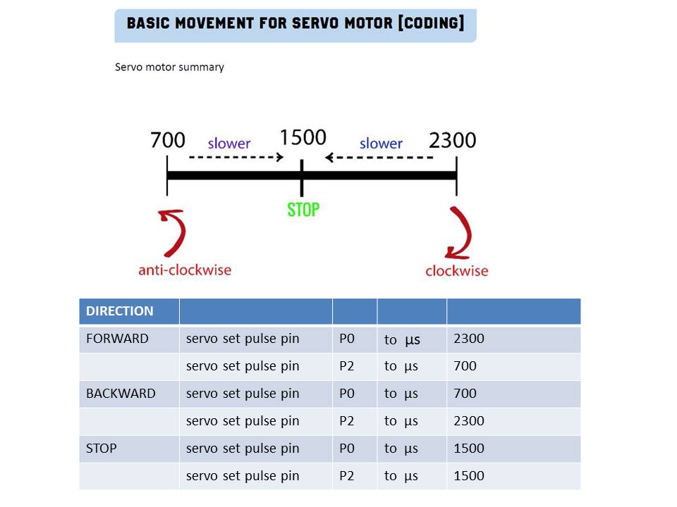
- Click at the “Pins” tab and select block “servo set pulse pin”.
- Set the pulse width for pin P0 to 2300 and pin P2 to 700 in order to move forward.
- Put the configured “servo set pulse pin” into block “on button [A] pressed”.
- Repeat step 1 until 4 with button B and set the pulse width for pin P2 to 2300 and pin P0 to 700 in order to move backward.
- Flash the configured blocks into the micro:bit and run the servo motor.